I replaced the diode bridge (B250) on the take up motor’s control board. Then I performed two tests. The first was where I threaded tape as soon as the machine was turned on and let it play. After more than half a 7″ reel at 15IPS, the motor was cool as a cucumber. Another test later was to first let the machine be on for a couple of hours, then play tape. The motor’s casing got a little warm, but nothing like before. I think the little bit of heat is from the two big transistors that are mounted on the heatsink right next to it.
By the way, the old bridge tested fine out of circuit, but I guess it cracks under high voltages.
I think I’m going to replace the diode bridges on the other two boards, because why not.
My “fix” from the last post didn’t actually take. The -12V rail kept dropping randomly, and I isolated it to connector 3 on the transport board – disconnecting it restored the voltages. I asked about it in the Studer group, and people were saying that the low voltages shouldn’t be what’s causing the the transport to misbehave since they’re not low enough. I also got more concrete suggestions like replacing the 4558 chips and inspecting the capacitors. I replaced the 4558s and inspected the capacitors (if you’re just reading this post, the whole machine has been recapped), and I’m not sure if that fixed it, or if the machine is fixed at all. When I turned the machine on after replacing the chips, the -12V rail was low. However, when the transport card was out, I also replaced the two brake drums with each other, and then just threw on the brake harness on without really adjusting the distances. I’m not sure why, but I think if the brake belts are misaligned, then it somehow affects the voltages. So basically, I’m not sure if this particular issue with the machine is fixed or not. For the past couple of days the -12V rail has been sitting steady at exactly -12V, and the transport hasn’t been misbehaving the way it has before.
Since the machine seems to be OK, I threaded at 7″ reel and played it at 15IPS. After playing half the reel I noticed that the take up motor is getting pretty hot. In that same thread I linked above, it was recommended that I check the brake belts as they may be impeding the movement of the brake drum. This is where I get confused. When engaging PLAY, the brake belts still slightly touch the drums. I was told that a 64th” of a gap is enough, but then the belts touch the drums in some places. So what gives? I have no clue. I did test how long it would take the motors to slow down if I hit play, then keep the brakes disengaged, but let go of the play button. It took the take up motor 2:22 minutes to come to a full stop while the supply kept going for 30 seconds more. So obviously the take up motor is being slightly more impeded by the brakes, but is it enough to warrant its heating up? This isn’t a rhetorical question, I actually want to know! EDIT: Got an answer from the Studer group. When they say the brake bands are impeding the motors, they mean the motor stops after 5 seconds with the brakes disengaged.
Another suggestion was to replace the B250 diode bridge in the motor control board, so I’m going to try that next. Those little boards are a pain to take out.
Basically this post contains no useful information as to how these machines should work!
Other tech/studio shit: I blew my Dynaudio’s tweeters by accidentally leaving a microphone open while listening back to a take. It was a short, quick feedback, and then I noticed that the tweeters distorted when I played piano through the speakers. I’m ordering new tweeters and woofers (the woofers got damaged in shipping, but still work, long story), and hopefully they can find crossovers in stock. I want to use these speakers for the next ten years.
Meanwhile I brought my B&W 805s into the studio. Then I noticed that they too have a quiet fuzz when I play piano (different from the Dynaudios though). Now I started thinking maybe there’s something wrong with my amp (Adcom GFA 555 II)! Could it be slowly frying my speakers? Or am I just unfortunate and both sets of speakers are acting up at the same time? I tested the amp for DC offset, and it has maybe about 1mV of offset which I think is not enough to fry a voice coil. I also tested the amp with a dummy load (using one 4 ohm 100 watt resistor per side). It has no crossover distortion or any other distortion. So I think the amp is fine. It’s also maybe worth mentioning that the B&W artifacts come through the woofers and not the tweeters. Here are a couple of photos:
Adcom left channelAdcom right channel
An interesting thing I noticed is that above 5kHz, the left channel is slightly louder than the right. Like, a 0.1mV difference.
I’ll update on the Studer when I know more. But basically my attitude is that if I can’t get a problem to reproduce I’m just going to go ahead and keep restoring the machine. Whatever issue is with the voltages will sooner or later show itself more consistently.
So first the good news, and it is that the capstan locks to all the speeds, and since the voltages were right I was excited thinking this machine is now working right mechanically. However, when I put a reel of tape on, I saw that the machine won’t rewind or fast forward unless I hold these buttons down.
I checked the voltages again and the -12V rail is down to -11.38V or so. Too low, so I started futzing around and found out that if I unplug the the connector above the brake bands (I need to figure out what it’s called) then the voltage was restored. It’s been working since, but I hate fixes like that. I feel like a dodgy connector will come back to bite me in the ass.
Slow FF was fixed by adjusting the FF trimmer in the card cage. That prompted me to adjust the tape tensions, and I’m unclear on how to perform the PEAK adjustments. Also when most of the reel is on the supply side, the take up tension roller jumps when I hit play. I might leave these adjustments to when I put the machine in its cart.
Will update here when I figure out how to do the PEAK adjustments.
Installed the new pinch roller assembly. Nothing tricky there, the only thing is that it requires ball-head allen wrench (should allen be capitalized? who’s to say!). I need to get a metric set of those. It’s still possible to get around it without a ball-head wrench. No pictures of the new one assembled, but here’s a picture of the machine without a pinch roller assembly at all!
No PR assembly!
To install the pinch roller assembly I had to remove the headblock connector from the machine’s chassis, and by that I mean that I just had to remove two screws. So then after I put the PR assembly in, I made sure the headblock meets its connector right (is that a db25?). It does, because the screws that hold the connector to the machine have give to them, so the connector moves to meet with the headblock. Maybe this picture will do a better job explaining.
No front tape transport cover.
I also got the new capacitors for the power supply and put them in. Per my last post, I already recapped the PSU, but I used snap-in caps, and they don’t really sit very well on the PCB. I got normal through hole capacitors and they are better secured to the PCB than before.
Beautifully mounted filtering capacitors. Maybe they’re a bit too close to the PCB? Not going to worry about it now.
The problematic voltages before were the -12V and +5V, now they measure -11.93V and 4.97V respectively. Now how low (or high) a voltage from the rated spec is ok? I don’t actually know, but these are within 1% of the nominal voltage, and I believe that’s good enough.
I also adjusted the brake belts on both motors. I think that that and the right supply voltages should fix the capstan motor not locking into any of the speeds, but I need to install the capstan motor and test it before I post about it.
Also, I would love a small Studer broadcast console to go along with my B67.
It’s been almost three years since I posted here! I’ve worked on a few projects since then, mostly mine, but a few were for other people. Part of the reason as to why I stopped updating here is that I shifted my focus to working on music as my full-time occupation. I’ve worked on some music for TV and films, recorded and mixed a few records, and last year I put out my first solo release, available here.
During the pandemic down-time I’ve gotten back to some of my shelved projects, most importantly my Studer B67, and found myself going back to so many of my entries here, most of them were very useful. So I figured it’s a good idea I to keep updating for my future self’s sake!
Ok here’s the work I’ve done on my Studer in the past couple of months.
I sent the capstan motor to Athan to get it rebuild and resurfaced. I also ordered from them new bearings for the guide rollers (the big ones) and the reel motors, and a new pinch roller.
Removing the old bearings can be a bit of a struggle. For the reel motors it’s not too big of a deal: The old ones can gently be pushed out with a pencil or something else like it. It’s important to keep the correct orientation of the cupped washers (also called pre-loads). The manual shows the correct orientation so it’s not big deal if you forget.
The big question though is should the motor shaft and washers be cleaned of the old oil and grease? And if so should they be lubricated again before installing the new bearings?
There’s no one clear answer. It seems that the thick residue is grease that leaked out of the old bearings, but there’s also some other lubricant there that seems to not be actual grease. Here are three answers I got:
George at Athan says he cleans off all the oil and grease and puts everything back together with the new bearings.
Jonathan Prager said he believes the shafts were lubricated with some oil originally, but he doesn’t know what. He said that the amount of lubrication that’s found inside can’t be all from grease that leaked from the bearings. He recommends cleaning off the grease, but keeping the oil that’s on the shaft.
John Chester’s (of the Plangent Processes and all around tape machine wizard) answer was the following:
Ideally there would be no lubrication there. The inner race of the bearing should be locked to the shaft. However, if the bearing is a very tight fit on the shaft, I will apply a drop of oil on the shaft, and then wipe it off, leaving a thin oil film. This often makes it easier to slide the bearing onto the shaft while applying as little pressure as possible to the balls. If it still won’t slide on, then I heat the bearing so that it expands slightly. Use a hair dryer or a heat gun set on low. Don’t get it up to finger-burning temperature, to avoid losing any lubricant.
John recommends using Zoom Spout Oil (light turbine oil with no detergents). Like the one found here. In case this link died, it’s theZoom Spout Oil with part number ZS 75A.
Getting the old bearings out of the big rollers was another story. The 40 year old aged grease and lube acted like some kind of glue and it was impossible to pull out those bearings. My solution was to pry open the top bearings. I removed the retaining ring, then pulled out the cover so I could see the balls.
The old bearings would not come out, so they were pried open and pulled out. You can see the balls inside and the lube/grease that turned gooey.
Now using pliers I grabbed the bearings by the inner circle and pulled out. At this point everything else came out easily. I cleaned off the old lube and grease and installed the new bearings. Now keep in mind, once everything is cleaned and installed back in, it comes out very easily! I had a couple of mishaps were basically the contents of the roller just spilled out because I held it wrong. I think everything in there is OK, but just be extra careful with it. And again, remember that the preloads (the cupped washers) have a certain orientation for them!
As far as the rollers and motors, I think everything is working ok, except for the supply motor which has a bit of a wobble. I think I’ll run it without the brake drums and bearings and see if the axle itself has a wobble to it or what.
Next came the capstan motor reinstall. Unfortunately I simply installed it on, and then the heastack and I did not notice that the inner curve of the headstack chassis was touching the capstan motor. Once I turned the machine on, the capstan was literally grinding against the chassis, and the result is this:
What happens when you incorrectly install your newly refurbished and resurfaced capstan motor. Luckily that’s not where the tape touches.
How do you avoid this? Athan put a heatshrink tube on the shaft. I should have kept it on until I was ready to run the machine. In fact that’s what I do now. I keep the shrink on until everything is in place the correct way. So get some heatshrink and place it on the capstan’s shaft!
Now when installed the capstan motor itself, it needs to be pushed up and towards the supply reel. It’s a bit difficult to do when the machine is upright because it’s such a heavy motor, so you might want to place the machine on its side.
The next ordeal was when I installed the new pinch roller. It did not want to go on the assembly’s shaft. I cleaned the shaft (which was pretty clean to begin with) with the Athan supplied sandpaper, and that didn’t help. Following George’s recommendation to slightly lube the axle, I did and got the roller on. However, there was no pulling it out. Seriously, the thing was there for good. Of course this is a problem because I had the front shield and the headstack on. And not only that, I needed to adjust the brake bands. This caused me a lot of grief and the only way to remove it was through the back of the machine. So I had to remove the capstan motor (for the 10th time), and get a special wrench (the nut is M4 and requires a 7mm wrench). Pushing the pinch roller up from the front, I started loosening the nut on the back. However, at some point the nut seized and wouldn’t go further. Long story short, I ended up using vise grips to grab the pinch roller shaft from the front, and using the wrench in the back I was able to remove the shaft. The nut ate through two rows of the threading on the back of the shaft. Check it out:
The back end of the axle. See the ruined threads.
Front end of the axle with the threads ruined by the pliers and vise grips.
The pinch roller would still not come off. I sent the axle and pinch roller to Athan who separated them and sent them back. Obviously this axle is gone, but luckily for me I was able to find another B67 pinch roller assembly on eBay. The pinch roller goes on smoothly on the new assembly.
Here are my takeaways from this particular ordeal:
At first tried using pliers to grab onto the front of the axle. I padded the teeth with leather and grabbed the by the threads. It didn’t work. I should have used vise-grips with leather padding from the get go. The vise-grips are a better tool because you can tighten the grip.
Don’t install a new pinch roller with the front tape transport cover and headstack on. First try it without any of this stuff, so that if there’s an issue the whole pinch roller assembly can be removed.
Two more issues which I hope aren’t a big deal. First the capstan motor doesn’t lock to any speed. From reading online I believe that this is because the supply motor brake belt is loose. The other issue is that the -12V and +5V rails are reading a little too low. The -12V rail reads -11.3V and the +5V reads 4.4V. I thought the issue is at the transport PCB, but then when I went to remove it, the 10mF capacitor at in the power supply (aka Stabilizer) literally came off. This is cap uses snap-in legs and they are too short. I soldered it back and the voltages read -11.9V and 4.9V. I ordered non snap in capacitors for the power supply because I don’t trust these snap-in legs in this application.
My last advice/epiphany is that when removing or installing any screws, washers, and nuts it is best to keep a piece of paper inside the machine under where the screws go. I lost a couple of washers inside the machine which had me holding the machine up in the air over my head and shaking it until the washers fell out. Is it dumb? Yes, don’t do it. Did it cause that 10mF capacitor to come undone. Most likely.
This turned out longer than I hoped. I’ll do another post about the highlights of my other projects from the past three years.
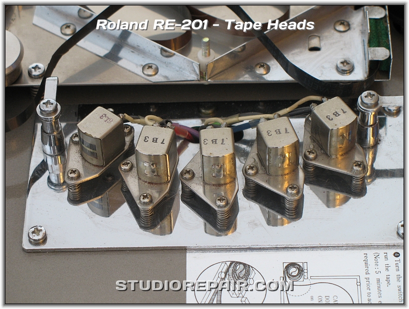
I was looking to buy a local Space Echo to fix and flip, but I didn’t because the erase head looked like this:
Notice the line going down the middle of the erase head.
That line going down the middle of the erase head gave me cold feet, because if I learned anything from tape machines is that heads wear and eventually open up and the gap between the poles shows, and presumably that is what I was seeing here. So I started looking online for examples of RE-201 erase heads. Here’s what I found:
See the line going down the middle of the erase head here
Kind of hard to tell, but there’s a line in the middle of the erase head
The line down the middle of the erase head is very visible
Even though this picture isn’t the best, there’s no line down the middle of the head
Same headstack as in the last picture. No line.
My friend’s RE-201. Notice the line.
So as you can see, most heads have a line. The Echo shown in pictures 4 and 5 don’t have a line down the erase head, but these are also a bit blurry, so maybe I’m just not seeing it. So maybe all these are examples of heads that started to go, or maybe that’s just the design? I emailed the folks at soundgas.com to ask for their opinion. If you’re not familiar with them, they refurbish and sell a lot of different tape echoes, so I figured they would know. And they did. Here is their response:
A very thin vertical line should be there – it’s the dividing line between the two poles of the head. However you shouldn’t be able to feel it – if you can then the head is not right.
So indeed this is the line between the two poles, but IT IS normal for it to show. And there’s even a little method of testing it. I’m still a bit unsure about this being the design of the heads, but at the same time, the unit I was looking at was erasing, and probably so are all the other examples I found online.
Photo credits: First (Soundgas LTD), second (stuffandfood.wordpress.com), third (StudioRepair.com), fourth and fifth (stickylight.wordpress.com). I only download and re-upped these photos in case those sites ever go down.
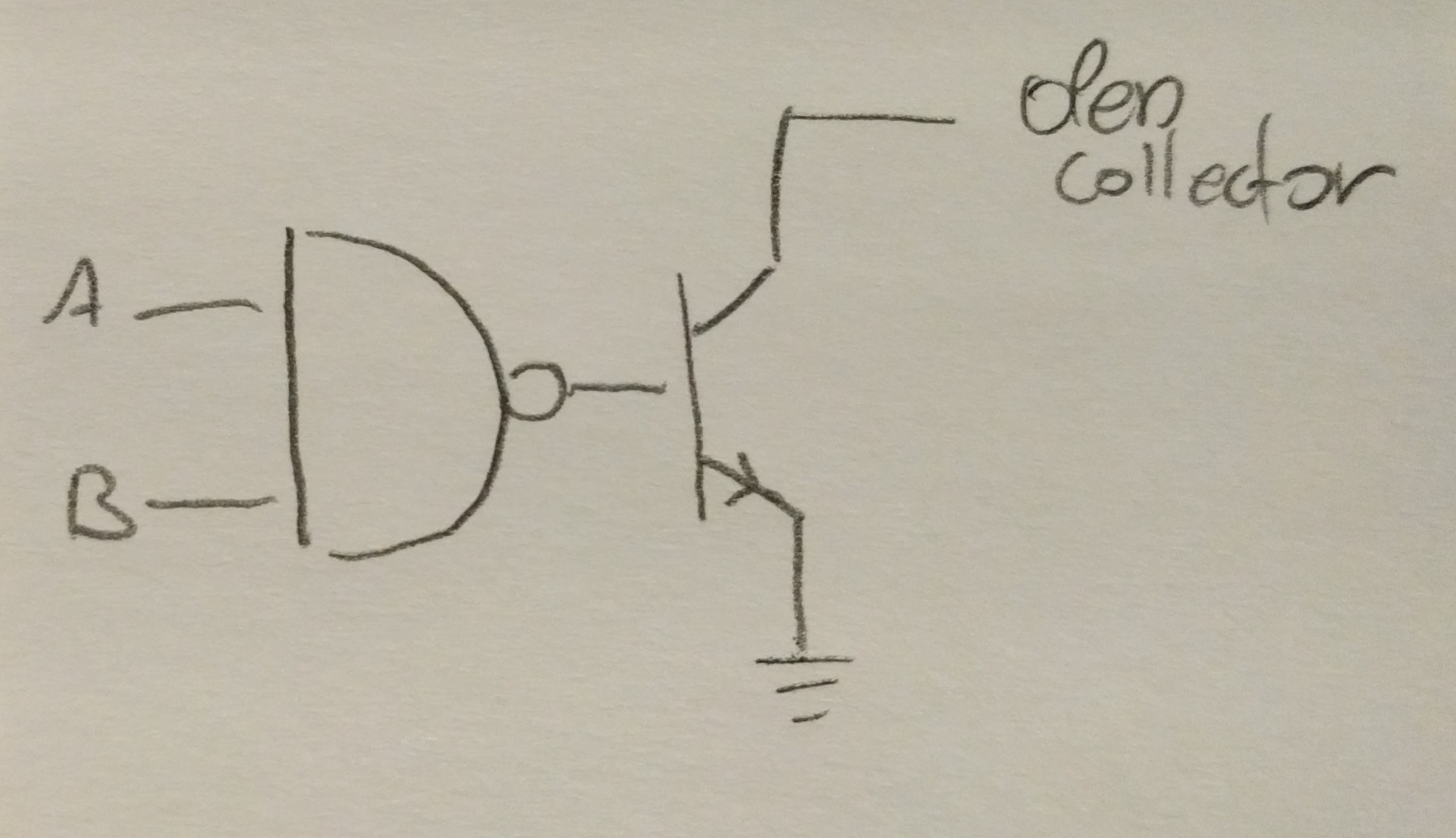
I explained two posts ago that the problem with this tape machine was IC 3, an SN75462 that was put on backwards and therefore fried. That IC was responsible for interpreting logic from the transport and operating the tape sensors’ locking solenoids. Here’s the data sheet for the SN75462, and I can’t say I understand it all, but the gist of it is that it has two NAND (or AND) gates followed by an NPN transistor whose collector is taken to a pin on the actual chip, so it’s not necessarily connected to Vcc powering the chip. This is called an open collector, and here’s a very good explanation of what it is, and what are some applications. Here’s a little drawing of what this looks like in this particular case (can also be seen in the data sheet):
Here’s the portion of the schematic that shows IC3 in the circuit, the anode of the zener (D59 in this case, but all of them do) goes to ground.
Now, when I was measuring the voltage at pins 3 or 5 of IC3 (after it’s been replaced with a functional one), what I saw was that it was “delivering” +24V when it was supposed to deliver +5V (Vcc), and that was very confusing because how could it put out such a high voltage when Vcc is 5V? Not only that, the +24V was identical to what I was seeing on the other side of the relay (that should have tipped me off..)
The answer to this is the open collector but also a KVL of the circuit. I was thrown off before because someone mentioned off-hand that the reverse diode pulls up the voltage, and that sent me on the wrong path for a while. I finally understood what’s going on when I drew the NAND gate + the transistor + diode + relay together:
Here’s how I understand it. When the transistor is ON, the collector is pulled to ground through the transistor, so current flows through the relay. When the transistor is OFF, no current flows through it so the collector is free to being pulled up. What does it mean, though? KVL shows it. There’s +24V on one end of the relay, but no current flows through it (the transistor is OFF and the zener is reverse biased), so there’s +24V on its other end. That other end is the collector, and that’s why I was seeing the exact same voltage on both ends of the relay.
Now, one might ask why use the zener at all? Pull it out of the circuit and you get the same behavior. However, when you open the switch connected to a relay, the relay shoots out a spike of high voltage. Without another path to ground, that voltage will fall on the transistor and burn it. Instead, the zener starts conducting as soon as the voltage across it is higher than 30V. A regular diode reverse biased won’t work because it won’t recover from being pushed to its breakdown region. And of course, a forward biased diode will always conduct so current will always flow through the relay.
Not a lot of updates. I’ve been rearranging my workspace/studio and there’s nothing too exciting about that. However, I did clean the faceplate of the B67 as well as the knobs with hot water and dishwashing soap. It made a pretty big difference:
Before
After (not the same side, but you get the idea)
Under the knobs there was this grease that I couldn’t identify. It wasn’t grime from years of neglect, but rather grease that was put in place either at the factory or at some point when someone serviced this machine. I cleaned it off for now and I’m going to figure out if it actually needs to be replaced.
Other than that, I noticed that the tape path is a bit misaligned and the tape doesn’t pass right over the heads the way it should. Will deal with that when I’m done reorganizing. Then I hope to order capacitors for the audio electronics if I have time before the week ends.
This time for real. The SN75462 replacements got here yesterday and I popped on in IC3’s socket and the machine works. The sensor lock in STOP and the motors are both responsive. Here, see for yourself:
There are a few things I need to figure out for next time I look under the hood:
Does J3/4-6 provide the +24V to the solenoid?
EDIT: Yes. Look at the schematic. J3/7 is connected to the +24V through the power ON/OFF switch. The other end of the switch goes to J3/4-6. So one end of the solenoids is fed directly from the +24V rail.
Does K-EDIT deliver exactly the same voltage as what comes from the +24V rail, or is it something like ~25V (the Zener diode “trick” so that it looks like the output of IC3 is ~25V instead of 5V)?
EDIT: The fast answer is that K-EDIT gets exactly what the other end of the solenoid is fed, because of KVL. See here for the longer answer. There’s no zener “trick” so to speak.
Does the voltage at IC 4 pin 1 equal to the voltage on pin 7? That is, does it work like some kind of a comparator? See previous post and notes I left in the manual.
I was in the middle of writing a progress post and then I went to probe around IC3 in the transport and realized that IC3, was put in the other way around. That is, pin 1 is where pin 8 should be, etc. I flipped it around and it is now fixed! Here’s a more detailed explanation of what I’ve done in the past few weeks:
First a recap of the problem: Upon turning the machine ON, only one motor will be responsive to the transport controls. For instance, pressing PLAY would make the take up motor spin but not the supply. Then if I spun the roller on the right clockwise, the take up motor would turn off and the supply would turn on and start spinning. Spin the roller counterclockwise and now the take up would run and the supply motor would shut down. Even weirder was that disconnecting the J5 connector from the pre-divider board caused the machine to operate correctly.
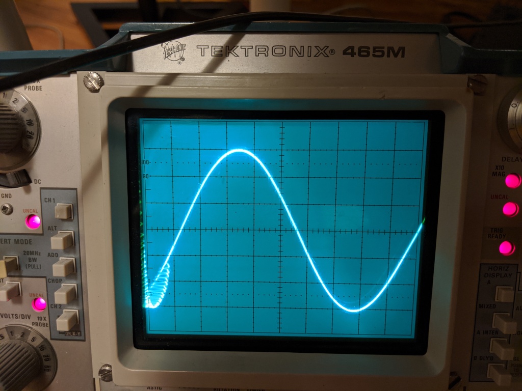
So when I picked up troubleshooting the machine again I decided to go over the counter’s schematic to try understand better what’s happening with QP-DIR1 and QP-DIR2. To be honest, I’ve done that before, but this time I also graphed the waveforms along the way from where the signals come into the board, and their way to becoming Y2-FORW and Y2-REVS. I also keep these drawings with the manual for future reference. That didn’t tell me much other than that when the roller on the right is spinning clockwise, Y2-FORW goes HIGH and when it’s spinning counterclockwise it’s going LOW and Y2-REVS goes HIGH. I also realized (might have before as well) that the pre-divider carries these signals FROM the counter TO the transport.
Advice on the tapeheads.net reel-to-reel forum directed me to the tension sensors, so I started learning the circuit comprised of ICs 4, 1, 6, and 2. That made sense to me because that circuit is responsible for generating the pulsating signal that controls the motors. My understanding of how IC4 is used is that it is some kind of a comparator. So depending on YAN-TT1 and YAN-TT2 it’ll go positive or negative. That’s how the lower half of IC4 (YAN-TT2) was acting and that made sense. However, the voltages from YAN-TT1 weren’t enough to cause the comparator to work the right way. Instead it went from +12V to something like -2V. (By the way, that’s still how it is!) I thought that since this voltage is dependent on the displacing of the tension arm, that maybe its mechanical settings are out of wack.
So I took out the left sensor and adjusted it per the manual. I put it back in the machine and now both left and right sensors were locking in place. This one made me scratch my head, but it led me to start figuring out what’s controlling the solenoids of the two sensors. This stuff isn’t mentioned in the manual, so it took a bunch of probing and continuity tests to realize that the solenoids are fed the unregulated +24V and the respective outputs of IC3 (SN75462). I mentioned that to a friend and he said that IC3 goes bad often, so I put in an order for replacements. Meanwhile I went to check the voltages at the inputs and outputs of IC3 to see if it’s working right and that’s when I realized that it was put on backwards. I flipped it and now not only are the sensors not locked, but BOTH motors are responsive to the transport controls!
However, the sensors should lock when the machine is stopped. A quick check of the voltages in and out of IC3 showed that it’s not functioning right – it’s a NAND gate but when both inputs voltages are high (IC7 pin 7 is HIGH meaning the machine is stopped, and then a signal derived from pin 7 also HIGH) I get +24V at its output, but it should be 0V. It’s a good thing I ordered some SN75462 so I’ll drop a replacement in and see what’s up.


\" href=\"http://www.aliens-project.de\">Aliens Project</a>")


